

- Stock: In Stock
- Brand: rhydoLABZ
- Model: INT-2576
- Weight: 0.08kg
- MPN: INT-2576
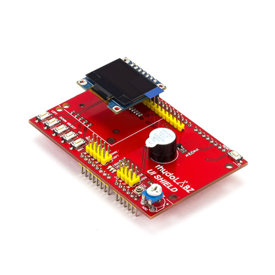
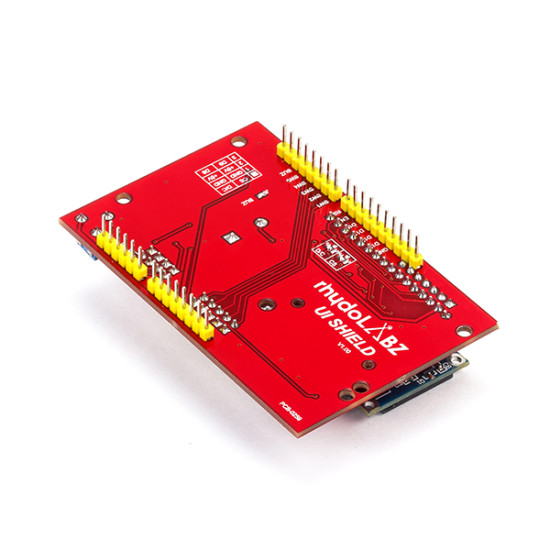
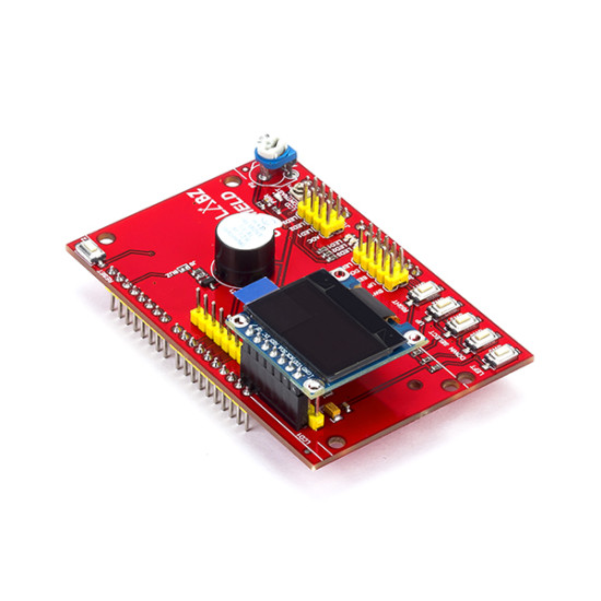
The rhydoLABZ UI Shield provides an easy way of interfacing OLED display modules with your Arduino boards. It features a monochrome OLED (0.96") display module, along with 5 keypad pins and few other added features. The 4 directional buttons plus select button allows basic control input. This feature packed shield, coupled with convenient display module, makes an ideal platform to build a stand-alone project with its own user interface.
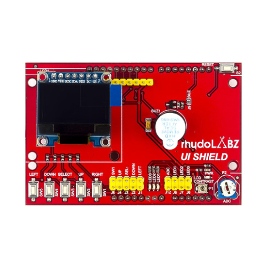
The communication interface between the OLED display and the controller is via hardware SPI pins of the Arduino. Both the DC and CS signals of the display module are jumpered on the shield PCB for easy hardware configuration. Reset pin (RES) of the OLED module comes in connection with D10 of the Arduino. DC signal determines whether the transferred data is written to display data RAM or command register. You could use the SPI library provided under the resources tab below to display alphabets, numbers, symbols, images and anything once you know to handle the pixels.
Additionally the shield also supports standard character display (16x2). A character display can be used in 4 bit mode saving a few of your output pins, a contrast adjustment trim-pot is also provided for the same. Apart from the display interfacing, it has input switches, on board buzzer and LEDs. Shield uses the digital pins D8 to D13 for LCD interfacing, D3 toD7 for keypad buttons and D2 for buzzer. Analog pins A2, A3 and A4 are connected with LEDs, A0 comes in connection with a preset; put to use the ADC functionality. Arduino reset switch is brought out on the shied for easy accessibility.
This product comes as a kit! Includes high quality PTH PCB, 0.96" OLED display and other onboard features (buttons, buzzer, header etc). Most of the connections are jumper selective which makes it apt for prototyping as well. Ultimately rhydoLABZ UI shield is the super slick way to add a display without all the wiring hassle on your Arduino.
NOTE: The images sport out 1.3" monochrome OLED display, but the shield actually accompanies 0.96" monochrome OLED display.
Features:
- Operating Voltage: 5V
- Comes with a 0.96" OLED Display
- 5 Momentary switches for custom menu control panel
- RST button for resetting arduino program
- Supports OLED Display (0.96" and 1.3") , SPI interfacing
- Supports 16x2 Character display, 4bit mode
- Trimmer resistor for varying analog input
- On board buzzer for audio alert
- Plug and play with any Arduino
- Mounting support for display modules
- Professionally Designed High Quality PTH PCB
- Dimensions: 81.4x53.5 (MM)
OLED Display Specification:
- OLED Driver IC: SSD1306
- Display Pixel Color: Blue
- Resolution: 128 x 64
- Visual Angle: >160°
- Compatible I/O Level: 3.3V, 5V
- Mini Size: 2.7 x 2.8 (CM)
Jumper Connections:
| Jumper | Description |
| J1 | Enables/Disables 'Left' Switch |
| J2 | Enables/Disables 'Down' Switch |
| J3 | Enables/Disables 'Select' Switch |
| J4 | Enables/Disables 'Up' Switch |
| J5 | Enables/Disables 'Right' Switch |
| J6 | Enables/Disables 'LED3' |
| J7 | Enables/Disables 'LED2' |
| J8 | Enables/Disables 'LED1' |
| J9 | Enables/Disables Buzzer |
| J10 | Configures DC pin of the OLED Display |
| J11 | Configures CS pin of the OLED Display |
| J12 | Enables/Disables analog input on A0 |
Pins Used:
| Pin | Description |
| A0 | Analog Input Pin connected to Preset |
| A2 | Connected to LED, LED1 |
| A3 | Connected to LED, LED2 |
| A4 | Connected to LED, LED3 |
| D2 | Connected to Buzzer |
| D3 | Connected to Switch, SW5 |
| D4 | Connected to Switch, SW4 |
| D5 | Connected to Switch, SW3 |
| D6 | Connected to Switch, SW2 |
| D7 | Connected to Switch, SW1 |
| D8 | Connected to OLED Pin, D/C |
| D9 | Connected to OLED Pin, CS |
| D10 | Connected to OLED Pin, RES |
| D11 | Connected to OLED Pin, SDA |
| D13 | Connected to OLED Pin, SCK |
Package Includes:
- 1 x User Interface Shield
- 1 x 0.96" OLED Display Module
- 9 x Jumpers - 2.54mm


