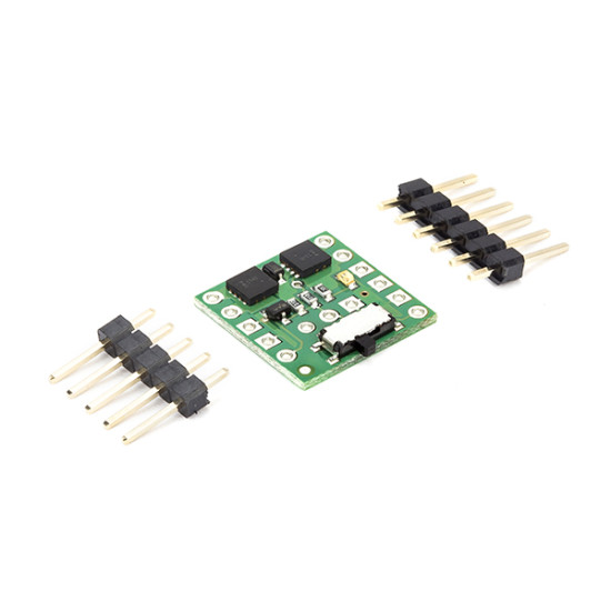
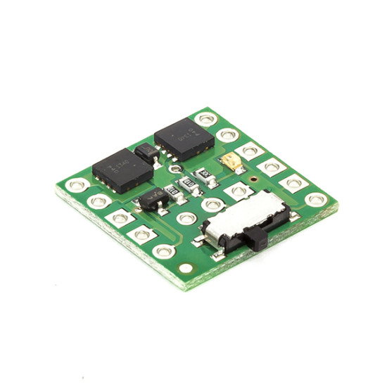
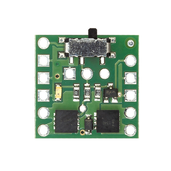


Mini MOSFET Slide Switch With Reverse Voltage Protection, SV
- Stock: In Stock
- Brand: Pololu - USA
- Model: ROB-2633
- Weight: 0.02kg
- MPN: 2811
Rs 299.00
(Excluding GST)
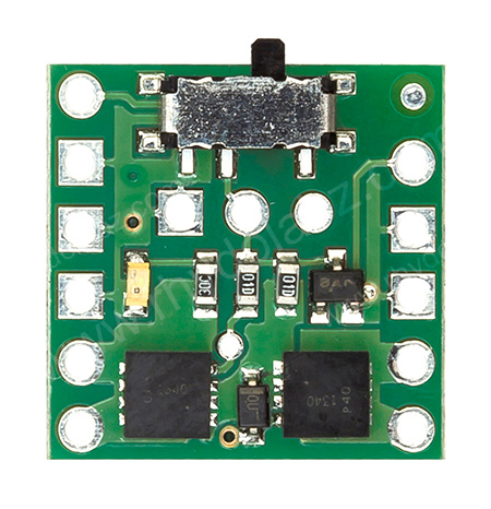
Description: This product is a power switch implemented as a pair of P-channel
MOSFETs configured as a high-side switch with reverse voltage protection
and controlled by a micro slide switch. Because the main current does
not go through the controlling mechanical switch, a variety of switches
can be used without concern for the current they can carry. For
example, a small slide or toggle switch can be mounted conveniently on a
control panel with thin wires running to it, while the main power path
can be shorter and with thicker wires. Pushbutton or tactile switches
can also be used for momentary switching applications.
Specifications:
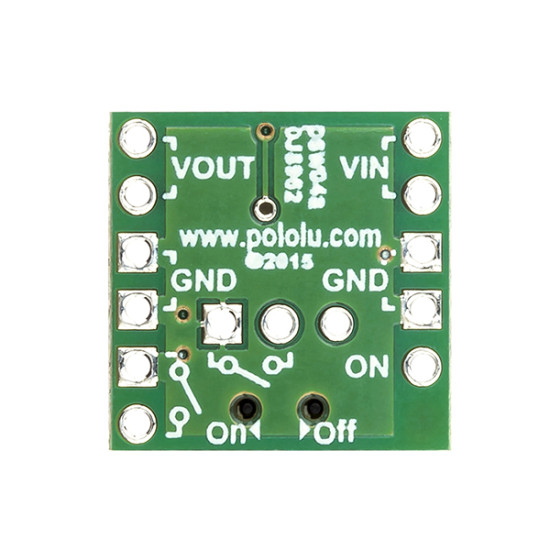
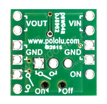
If the physical switch is in the "off" position, the switch state can also be controlled by a digital signal (e.g. from a microcontroller) via the "ON" control pin. Driving the "ON" pin low (or leaving it disconnected) will leave the switch off; driving the pin beyond approximately 1 V will turn the switch on. The maximum voltage for the "ON" pin is 30 V, independent of the switch voltage (VIN).
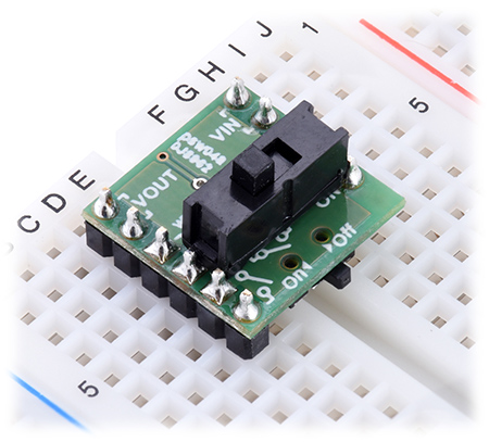
The MOSFET Slide Switch is compatible with solderless breadboards and perforated printed circuit boards with standard 0.1″ spacing. For such applications, the included male header pins can be soldered to the switch PCB. Alternatively, wires can be soldered directly to the switch PCB for non-breadboard applications. For high-current applications, make sure that the wires can safely carry the current. Two pads/pins are provided for each of the power nodes, and multiple pads should be used for applications drawing over 5 A.
Thermal and power dissipation considerations: Because MOSFETs in the on state are effectively resistive, the power heating the board is proportional to the square of the current flowing through it. The comparison table near the top of this page shows typical currents that heat the MOSFETs to 55°C, where the MOSFETs start being noticeably warm but are still generally safe to touch, and currents that heat the MOSFETs to 150°C, the absolute limit for the MOSFETs. With adequate cooling, or for brief periods if the MOSFETs are not hot to begin with, currents up to the listed maximums are attainable.
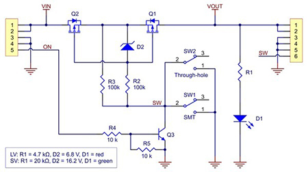
Schematic Diagram:
Dimensions:


Specifications:
- Absolute max voltage: 40 V
- Recommended operating voltage: 4.5 V to 32 V
- MOSFET combined on resistance (max)
- 90 mΩ @ 4.5 V
- 50 mΩ @ 10 V
- Continuous current at 55°C": 2.0 A
- Continuous current at 150°C: 4.3 A
- Maximum current: 7.2 A
- Current consumption in on state: ~65 μA/V
- LED color: green
- Reverse Voltage Protection: Yes

If the physical switch is in the "off" position, the switch state can also be controlled by a digital signal (e.g. from a microcontroller) via the "ON" control pin. Driving the "ON" pin low (or leaving it disconnected) will leave the switch off; driving the pin beyond approximately 1 V will turn the switch on. The maximum voltage for the "ON" pin is 30 V, independent of the switch voltage (VIN).
The MOSFET Slide Switch is compatible with solderless breadboards and perforated printed circuit boards with standard 0.1″ spacing. For such applications, the included male header pins can be soldered to the switch PCB. Alternatively, wires can be soldered directly to the switch PCB for non-breadboard applications. For high-current applications, make sure that the wires can safely carry the current. Two pads/pins are provided for each of the power nodes, and multiple pads should be used for applications drawing over 5 A.
Thermal and power dissipation considerations: Because MOSFETs in the on state are effectively resistive, the power heating the board is proportional to the square of the current flowing through it. The comparison table near the top of this page shows typical currents that heat the MOSFETs to 55°C, where the MOSFETs start being noticeably warm but are still generally safe to touch, and currents that heat the MOSFETs to 150°C, the absolute limit for the MOSFETs. With adequate cooling, or for brief periods if the MOSFETs are not hot to begin with, currents up to the listed maximums are attainable.
Schematic Diagram:

Dimensions:
- Size: 0.6″ x 0.6″ x 0.1″
- Weight: 0.6 g


