


ARM LPC2129 Development board Mini - rhydoLABZ
- Stock: In Stock
- Brand: rhydoLABZ
- Model: DEV-2589
- Weight: 1.00kg
- MPN: DEV-2589
Rs 4,499.00
(Excluding GST)
Description: The all New LPC2129 Development Board-Mini can be used to evaluate and demonstrate the capabilities of NXP LPC2129 microcontroller and CAN Communication. Since all I/O pins are broken out on Male and female Berg strips, it is very easy to use for development purpose as well. The board is designed for general purpose applications and it includes a variety of hardware to exercise ARM microcontroller peripherals. Onboard Mini Bread board is provided to ease the use, Ideally suitable for training and development purposes. Apart from this there is an onboard 2mm pitch Female sockets on both bottom and top side to insert Xbee module as per convenience .Since there are different modules (GPSBee, Bluebee, RFBee Etc) are available in the XBEE form factor, it will be easy to interface and experiment all of them.
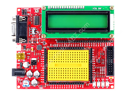
The board is populated with MCP2552 CAN transceiver IC and related components to enable the CAN Communication. The CAN pins are available at a 4pin RMC connector with VCC and ground. The onboard 5V regulator is having current rating of 1A and 3V3 voltage regulator is having 500mA capacity to easily power almost all onboard devices as well as external devices. All I/O pins and Power pins (5V & 3V3) are made available at Female header pins around the Breadboard to ease the wiring. Apart from this the all I/O pins are ready at male berg strips in two rows below the LCD. The UART0 & UART1 pins are available at separate RMC Connector with power (VCC & GND). UART0 is provided with onboard MOSFET voltage level converter with PCB jumper option to select the required interface voltage (3V3 or 5V). The onboard mini-B type USB connector can be used to power the board as well as to communicates with PC. A jumper is provided to select the PC interfacing method (USB or RS232).
The development board can be programed by ISP Programmer or separate JTAG programmer/debugger. A 20 pin shrouded male connector has been provided to connect JTAG programmer. In ISP Programming mode, user can select the desired interface (either USB or RS232) using the onboard jumper selection. A DPDT sliding switch has provided to select Automatic or Manual ISP Programming mode. Apart from USB the board has two more powering options like DC Adapter jack and 2Pin RMC connector with Reverse polarity protection. Available onboard peripheral interfaces are 3 nos Pull-up switches, 3 nos LEDs, buzzer, Analog Temp sensor, Analog POT, 16X2 LCD, RS232, USB, Voltage Level Converter and connectors for xbee, SERVO Motor, UART0, UART1, JTAG etc. All these peripheral interfaces can be disconnected by removing onboard PCB jumpers to free up the I/O PINS for other purposes.
NOTE: For code execution the ISP jumper should be removed other wise the controller will be reset continuously. For UART0 communication, the DPDT sliding switch should be placed in manual mode.
Features:
- Includes NXP LPC2129 Microcontroller
- Compact and Ready to use design
- Professional EMI/RFI Complaint PCB Layout Design for Noise Reduction
- High Quality Two layer PTH PCB
- No separate programmer required (On-Chip Boot loader)
- No Separate power adapter required (USB power source)
- RS-232 Interface (For direct connection to PC’s Serial port)
- USB Interface to connect to PC
- DPDT Switch for Manual, Auto Programming selection
- On Board CAN transceiver IC and related components
- On Board Mini Breadboard for experiments
- On Board Two Line LCD Display (2x16)
- On Board 3 LED Interface to test Port pin (with jumper select option)
- On Board Analog Pot interface to ADC (with jumper select option)
- On Board Analog Temperature Sensor Interface
- On Board Buzzer Interface
- On Board 3button Pull-up Keyboard interface
- On Board Reset Switch
- On Board Connector for SERVO Output
- On Board Connector to interface Xbee module on top/bottom side
- On Board Power LED Indicator
- Adapter (any standard 9-12V power supply) option
- All Port Pins available at Male Berg Strip
- All Port Pins available at Female Berg Strip around Bread board
- On Board JTAG Connector for Debugging/Programming
- On Board DB9 Connectors (for UART0)
- On Board USB Connectors (for POWER/UART0)
- On Board 4 pin RMC connector (for UART0) with 3V3/5V level converter
- On Board 3 pin RMC connector (for UART1)
- On Board 4 pin RMC connector (for CAN)
- On Board 1 Amp Voltage Regulator
- On Board regulated 3V3/500mA output
- On Board regulated 5V/1A output
- Can be used as main board for developing applications
- On Board JTAG Jumper
- On Board ISP Jumper for Manual Programming
- On Board 10 MHz Crystal Oscillator
- NXP LPC 2129 with 10 MHz Crystal Oscillator (With Boot loader Software)
- High Performance 32-bit ARM7TDMI-S™ CPU
- 256 KB Programmable Flash Memory provides a minimum of 100,000 erase/write cycles and 20 years of data retention.
- 16 KB Data Memory (SRAM)
- In-System/In-Application Programming (ISP/IAP) via on-chip boot-loader software.
- Flash programming takes 1 ms per 512 byte line. Single sector or full chip erase takes 400ms.
- Embedded ICE-RT interface enables breakpoints and watch points.
- Two interconnected CAN interfaces with advanced acceptance filters
- Four channel 10-bit A/D converter with conversion time as low as 2.44 us.
- Multiple serial interfaces including two UARTs , Fast I2C (400 kbits/s) and two SPIs
- 60MHz maximum CPU clock available from programmable on-chip Phase-Locked Loop
- Vectored Interrupt Controller with configurable priorities
- Two 32-bit Timers.
- Four Capture and four Compare channels.
- PWM unit with six output pins.
- Watch Dog Timer
- Up to forty-six 5V tolerant general purpose I/O pins.
- Up to nine edge or level sensitive external interrupt pins.
- On-chip crystal oscillator with an operating range of 1MHz to 30MHz.
- Two low power modes - Idle and Power-down.
- Processor wake-up from Power-down mode via external interrupt.
- Individual enable/disable of peripheral functions for power optimization.
- CPU operating voltage range of 1.65V to 1.95V and I/O power supply range of 3.0V to 3.6V
- 1 x Fully Assembled and Tested Development board-Mini
- 1 x RS232 Serial Cable DB9 M/F
- 1 x USB miniB Cable
- 5 x jumpers(2mm)
- 1 x Breadboard Mini Self-Adhesive (Yellow)
- 4 x Spacers
- 8 x screws
- 1 x 2-Pin RMC Female connector With Wire -2mm Pitch
- 1 x Software CDROM with
- Schematic
- Programming Software
- Sample Hex Code
- Example Codes
 , USB Connectivity, Plug-and-AI")


 - A7672S-LASE")

